Inertial Sensors
Inertial sensors are sensors based on inertia and relevant measuring principles. These range from Micro Electro Mechanical Systems (MEMS) inertial sensors, measuring only few mm, up to ring laser gyroscopes that are high-precision devices with a size of up to 50cm. Within this note, we will briefly summarize these cases of inertial sensors that are most important to the autonomous navigation of unmanned aircraft. Inertial sensors for aerial robotics typically come in the form of an Inertial Measurement Unit (IMU) which consists of accelerometers, gyroscopes and sometimes also magnetometers. Subsequently, we will briefly summarize the main principles of accelerometers and gyroscopes widely used in unmanned aviation.
Accelerometers
|
Accelerometers are devices that measure proper acceleration ("g-force"). Proper acceleration is not the same as coordinate acceleration (rate of change of velocity). For example, an accelerometer at rest on the surface of the Earth will measure an acceleration g= 9.81 m/s^2 straight upwards. By contrast, accelerometers in free fall orbiting and accelerating due to the gravity of Earth will measure zero.
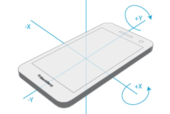
Accelerometers are electromechanical devices that are able of measuring static and/or dynamic forces of acceleration. Static forces include gravity, while dynamic forces can include vibrations and movement. Accelerometers can measure acceleration on 1, 2 or 3 axes. Currently, 3-axes devices are becoming more common due to the great cost reduction. Figure 1 depicts the axes found on such a device. It is highlighted that the accelerometer will measure according to its own body of reference and based on the effect of the external forces on it. |
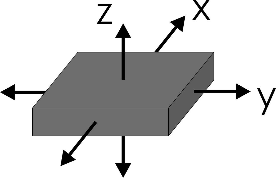
Figure 1: Axes of a 3-axes accelerometer.
|
|
A simplified accelerometer model is depicted in Figure 2. It consists of the mass (m), the spring-damper system (k,c), the transducer and the overall component is rigidly attached on a vehicle. The displacement of the vehicle from an inertially fixed point is denoted as d, while the displacement of the test mass m from its rest point is denoted as x. Therefore:
|
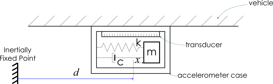
Figure 2: Simplified model of an accelerometer.
|
where α is the acceleration (second derivative of d). This essentially is a second order Linear Time Invariant (LTI) model. It has the vehicle real acceleration as an input and its output is the negative of indicated test mass displacement times k/m. Its block diagram is shown on Figure 3.

Figure 3: Block diagram of the simplified accelerometer model.
Note that for the cases within which, the vehicle acceleration is constant, then the steady state output of the accelerometer is also constant, therefore indicating the existence and value of the acceleration. Finally, as shown from the second order ODE above, the undamped natural frequency and the damping ratio of the accelerometer are:
Bias effects on accelerometers: accelerometer measurements are degradated by scale errors and bias effects. A typical error model takes the form:

where a3D stands for the 3-axes acceleration vector, Macc for combined scale factor and misalignment compensation, a3D^m for the measurement and abias for the measurement bias.
References and further readings:
- "Dynamics" course MIT OCW, Instructors: Prof. Sheila Widnall, Prof. John Deyst, Prof. Edward Greitzer, http://ocw.mit.edu/courses/aeronautics-and-astronautics/16-07-dynamics-fall-2009/
- Accelerometer entry at Wikipedia: https://en.wikipedia.org/wiki/Accelerometer
Gyroscopes
|
A gyroscope is - conceptually - a spinning wheel in which the axis of rotation is free to assume any possible orientation. When rotating, the orientation of this axis remains unaffected by tilting or rotation of the mounting, according to the conservation of angular momentum. Due to this principle, a gyroscope can lead to the measurement of orientation and its rate of change. The word comes from the Greek "γύρος" and σκοπεύω which mean "circle" and "to look" correspondingly.
Nowadays, we are mostly using gyroscopes that are based on different operating principles. In aviation we especially focus on MEMS gyroscopes or solid-state ring lasers, and fibre optic gyroscopes. In small-scale aerial robotics, we mostly care for MEMS gyroscopes. Gyroscopes are also called "gyros" in common everyday technical language. Figure 4 presents a 3-axes gyro component drawing. |
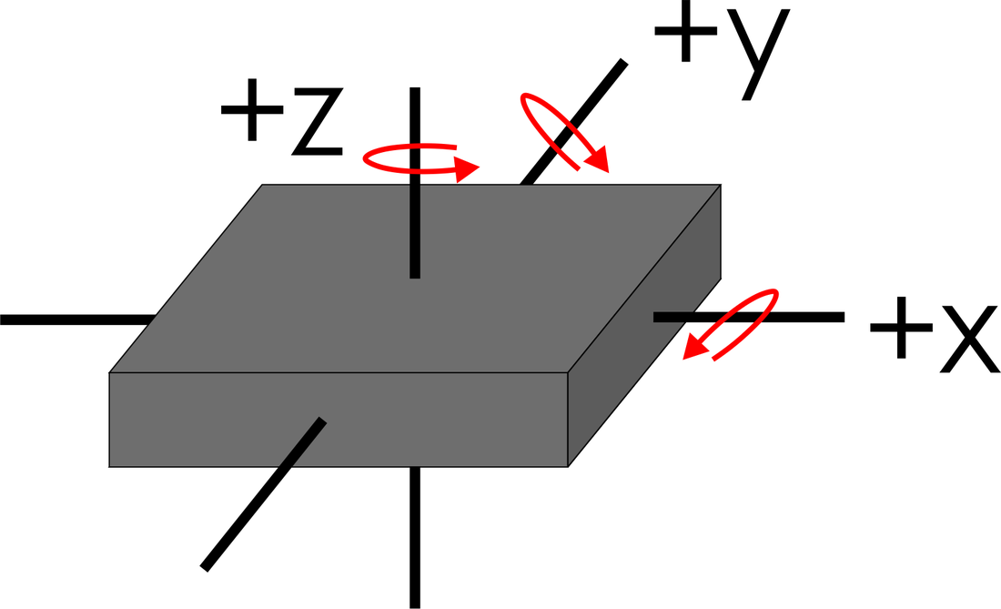
Figure 4: the 3 orientation directions measured by a 3-axes gyroscope.
|
|
To intuitively understand the operation of a gyro one can consider it being at the center of a rotating wheel. What will then be measured is the angular velocity of the z-axis of the gyro. The other two axis will then not measure any rotation or change of it.
A classical rotary gyroscope relies on the law of conversation of angular momentum. In simplified terms, this law states that the total angular momentum of a system remains constant in both magnitude and direction of the resultant external torque acting upon the system is zero. Gyroscopes exploiting this principle, typically consist of a spinning disk or mass on an axle, which is then mounted on a series of gimbals. Each of these gimbals provides the spinning disk an additional degree of freedom. Essentially, the gimbals allow the rotor to spin without applying any net external torque on the gyroscope. Therefore, as long as the gyroscope is spinning, it will maintain a constant orientation. In the case that external torques or rotations about a given axis are present in these devices, orientation can be maintained, and measurement of angular velocity can take place - due to the phenomenon of precession. |
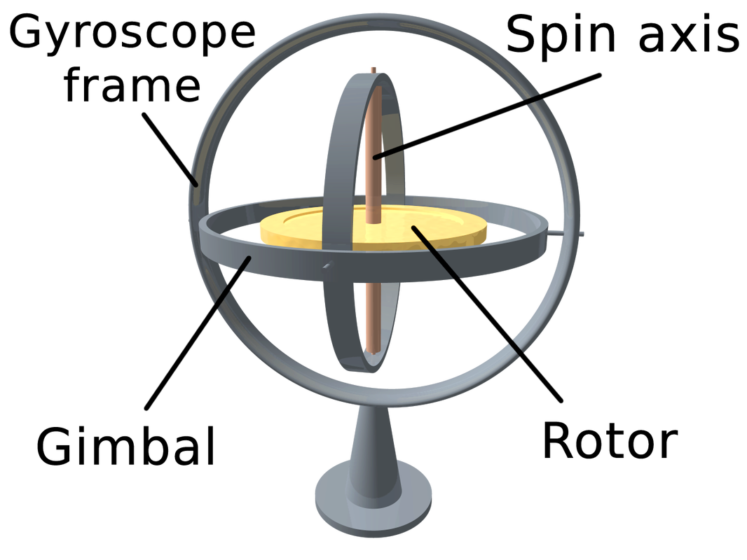
Figure 5: 3D Gyroscope. The image is reproduced from https://commons.wikimedia.org/wiki/File:3D_Gyroscope.png
|
The phenomenon of precession takes place when an object that is spinning about some axis (its "spin axis") has an external torque applied in a direction perpendicular to the spin axis (the input axis). In a rotational system, when net external torques are present, the angular momentum vector (along the spin axis) will move in the direction of the applied external torque vector. Consequently, the spin axis rotates about an axis that is perpendicular to both the input axis and the spin axis (this is now the output axis).
This rotation about the output axis is then sensed and fed back to the input axis where a motor-like device applies torque in the oppositie direction therefore canceling the precession of the gyroscope and maintaining its orientation. To measure rotation rate, counteracting torque is pulsed at periodic time intervals. Each pulse represents a fixed step of angular rotataion, and the pulse count in a fixed time interval will be proportional to the angle change θ over that time period. Therefore, the applied (known) counteracting torque is proportional to the rotation rate to be measured.
This rotation about the output axis is then sensed and fed back to the input axis where a motor-like device applies torque in the oppositie direction therefore canceling the precession of the gyroscope and maintaining its orientation. To measure rotation rate, counteracting torque is pulsed at periodic time intervals. Each pulse represents a fixed step of angular rotataion, and the pulse count in a fixed time interval will be proportional to the angle change θ over that time period. Therefore, the applied (known) counteracting torque is proportional to the rotation rate to be measured.
|
Vibrating structure gyroscopes are MEMS (Micro-machined Electro-Mechanical Systems) devices that are base their operation on a vibrating structure that exploits the phenomenon of Coriolis force. In a rotating system, every point rotates with the same rotational velocity. As one approaches the axis of rotation of this system, the rotational velocity remains the same, but the speed in the direction that is perpendicular to the axis of rotation necessarily decreases. Therefore, in order to travel along a straight lone towards or away from the axis of rotation (while being on a rotating system), lateral speed must be adjusted in order to maintain the same relative angular position (longitude) on the body. The Coriolis force corresponds to the product of the mass of the object (whose longitude is to be maintained) times the acceleration that leads to the required slowing down or speeding up. The Coriolis force is proportional to both the angular velocity of the rotating object, as well as to the velocity of the object moving towards or away from the axis of rotation. Figure 6 depicts the concept.
|
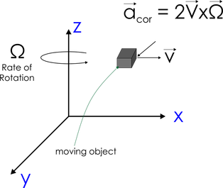
Figure 6: Coriolis force concept for the measurement of rotation rates.
|
|
As far as the actual way of implementing such a device is concerned, a vibrating structure gyroscope contains a micro-machined mass which is connected to an outer housing by a pair of springs. This outer housing is then connected to the fixed circuit board using a second set of orthogonal springs. The test mass is continuously driven sinusoidally along the first set of springs. As any rotation of the system will induce Coriolis acceleration in the mass, it will subsequently push it in the direction of the second set of springs. As the mass is driven away from the axis of rotation, the mass will be pushed perpendicularly in one direction, and as it is driven back toward the axis of rotation, it will be pushed in the opposite direction, due to the Coriolis force acting on the mass. Figure 7 presents a drawing of a MEMS gyro.
|
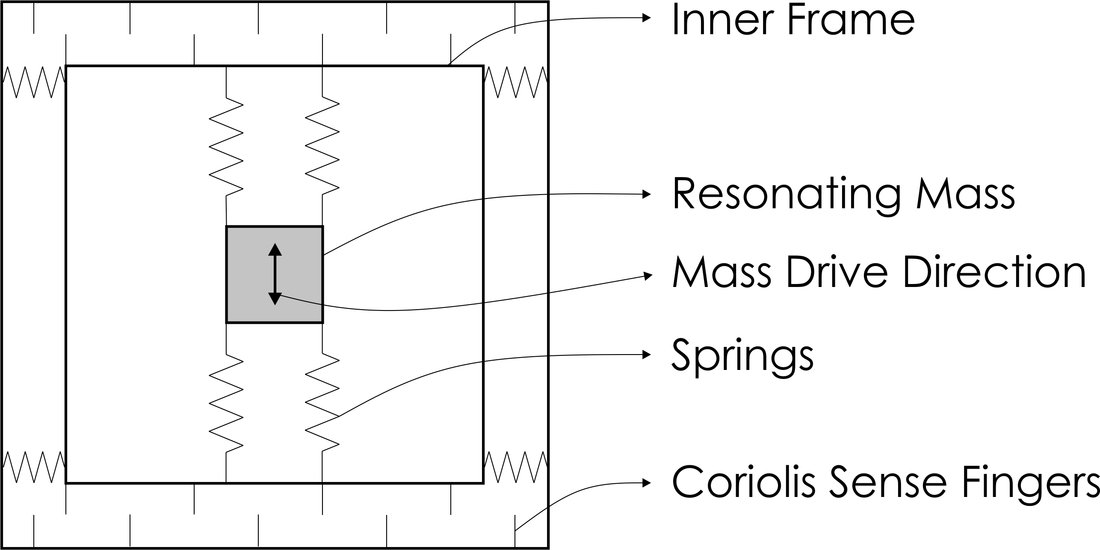
Figure 7: A MEMS structure-like drawing of a gyroscope.
|
The Coriolis force is sensed and detected by capacitive sense fingers that are integrated along the test mass housing and the rigid structure. As the test mass is pushed by the Coriolis force, a differential capacitance will develop and will be detected as the sensing fingers are brought closer together. When the mass is pushed in the opposite direction, different sets of sense fingers are brought closer together. Therefore, the sensor can detect both the magnitude as well as the direction of the angular velocity of the system.
Need for calibration: MEMS gyros are temperature dependent and have to be accurately calibrated prior to useful operation.
Bias effects on Gyros: The biggest problem with gyros (and what essentially constraints us from simply performing integrating actions on their measurements), is the existence of bias effects. Bias are mostly caused by:
- Drive excitation feedthrough
- Output electronics offsets
- Bearing torques
- Fixed bias ("const")
- Bias variation from one turn-on to another (thermal), called bias stability ("BS")
- Bias drift, usually modeled as a random walk ("BD")
where Q is known, with units of (deg/h)/sqrt(h)
Noise Model: A typical noise model that is employed to capture such effects on gyroscopes, takes the form:
Noise Model: A typical noise model that is employed to capture such effects on gyroscopes, takes the form:

It is highlighted that one must include the drift in the bias in the kalman filter dynamics.
References and other further readings:
- SensorWiki: http://www.sensorwiki.org/doku.php/
- Wikipedia entry on gyroscopes: https://en.wikipedia.org/wiki/Gyroscope
- MIT OCW - Aircraft Stability and Control - Lecture on "Inertial Sensors, Complementary Filtering, Simple Kalman Filtering"
Get the data from your phone
|
A smartphone integrates a pretty good - for its cost- Inertial Measurement Unit therefore giving access to accelerometer and gyroscope data. Getting intuitive understanding about sensor data quality is always of great importance. Feel free to use any of the free-ly available applications (e.g. "Sensorstream IMU+GPS" for Android) and use a piece of Python code, similar to the one below in order to get the data. This source code, comes from the example available at the "Sensorstream IMU+GPS" application website. Proceed and make a real-time plotting app for yourself. The image on right was found at "http://www.bbiphones.com/".
|
|
# Get the data and print them
import socket, traceback

host = ''
port = 5555

s = socket.socket(socket.AF_INET, socket.SOCK_DGRAM)
s.setsockopt(socket.SOL_SOCKET, socket.SO_REUSEADDR, 1)
s.setsockopt(socket.SOL_SOCKET, socket.SO_BROADCAST, 1)
s.bind((host, port))

while 1:
    try:
        message, address = s.recvfrom(8192)
        print message
    except (KeyboardInterrupt, SystemExit):
            raise
    except:
        traceback.print_exc()