PID Control
A Quick Introduction to PID Control
|
PID Control stands for Proportional-Integral-Derivative feedback control and corresponds to one of the most commonly used controllers used in industry. It's success is based on its capacity to efficiently and robustly control a variety of processes and dynamic systems, while having an extremely simple structure and intuitive tuning procedures. Although not comparable in performance with modern control strategies, it is still the best starting point when one has to start designing the autopilot for an unmanned aircraft. In fact, most existing attitude control functionalities found in commercial autopilots or open-source developments, rely on some sort of PID Controls. The structure of the PID controller is shown in Figure 1.
|
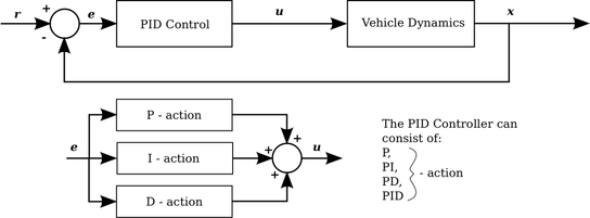
Figure 1: Block diagram of the PID Controller
|
The PID Controller consists of the additive action of the Proportional, the Integral and the Derivative component. Not all of them have to be present, therefore we also often employ P-controllers, PI-controllers or PD-controllers. For the remaining of this text, we will describe the PID controller, while any other version can be derived by eliminating the relevant components.
The PID controller bases its functionality on the computation of the "tracking error" e and its three gains KP, KI, KD. In their combination, they lead to the control action u, as shown in the following expression:
The PID controller bases its functionality on the computation of the "tracking error" e and its three gains KP, KI, KD. In their combination, they lead to the control action u, as shown in the following expression:
The proportional term corresponds to the first term of the expression on the right side, the integral action to the second, and the derivative to the last one. Each of these terms plays specific roles in order to shape the transient and steady-state response of the closed-loop system. More specifically:
|
Proportional Action: The P-action is the component mostly relevant with the dominant response of the system. Increasing the P gain KP typically leads to shorter rise times, but also larger overshoots. Although it can decrease the setling time of the system, it can also lead to highly osciallatory or unstable behavior.
Derivative Action: The derivative action responds to the rate of change of the error signal and is mostly relevant with shaping the damping behavior of the closed-loop system. In that sense, increasing the D gain KD, typically leads to smaller overshoot and a better damped behavior, but also to larger steady-state errors.
|
Integral Action: The integral action is typically employed to optimize the steady-state response of the system and shape its dynamic behavior. Essentially, it brings memory to the system. Increasing the I gain KI, leads to reduction of the steady-state error (often elimination) but also more and larger oscillations.
Collective Action: As understood from this brief overview of the role of each action of the PID components, one cannot independently tune the three different gains. In fact, each one of them aims to offer a desired response characteristic (e.g. faster respone, damped and smooth oscillations, near-zero steady-state error) but at the same has a negative effect which has to be compensated by re-tuning another gain. Therefore, PID tuning is a highly coupled and iterative procedure.
|
Summary of tuning tendencies:
| CL Response | Rise Time | Overshoot | Settling TIme | Steady-State Error |
|---|---|---|---|---|
| KP | Decrease | Increase | Small change | Decrease |
| KI | Decrease | Increase | Increase | Eliminate |
| KD | Small change | Decrease | Decrease | No change |
|
Quick & Dirty Tuning procedure:
|
Rigorous Tuning Methods:
|
Laplace form of the PID Controller: The PID controller is typically analyzed in the frequency domain, using its Laplace transform. The corresponding expression takes the following form:

A bit closer to real-life...
The PID controller is so successful both due its powerful performance and its simplicity. Nowadays, modern tools exist to optimally tune such control laws. Real-life implementation of PID controllers is however a much more elaborated process. Among others, the following important issues have to be considered when designing flight control functionalities using PID controllers:
- The control margins of the aerial vehicle have limits and therefore the PID controller has to be designed account for these constraints.
- The integral term needs special caution due to the often critically stable or unstable characteristics expressed by unmanned aicraft.
- With the exception of hover/or trimmed-flight, an aerial vehicle is a nonlinear system. As the PID is controller, it naturally cannot maintain an equally good behavior for the full flight envelope of the system. A variety of techniques such as Gain scheduling are employed to deal with this fact.
Interactive Demonstration
The following interactive demonstration is provided by Wolfram Mathematica:
PID Control of a Tank Level from the Wolfram Demonstrations Project by Housam Binous
Further Resources
The fact that PID control is so widely used, also means that several great tutorials exist. Among them, the following are some excellent examples that are worth going through:
- PID Control with MATLAB and Simulink - Excellent tutorial with several sections that cover both beginners' as well as expert's knowledge development.
- PID Control using LabVIEW - Another simple-to-go-through tutorial.
- PID Controller implementation using the STM32 family of embedded processors - An application note focused on embedded ARM processors.
- Multirotor PID Tuning Guide - A guide specifically for the Pixhawk Autopilot and multirotor Micro Aerial Vehicles.