Dynamics of a Multirotor Micro Aerial Vehicle
|
Multirotor Micro Aerial Vehicles (MAVs), systems with a diameter of less than 1m and weight no more than a few kg, are among the prevailing aerial robotic configurations of our times. The reasons behind this outstanding success are related with the mechanical simplicity and robustness, flight performance and agility, payload capabilities and more.
Multirotor MAVs are also relatively easy to model mathematically. A great deal of complex aerodynamic phenomena that one has to account during conventional helicopter modeling are negligible in small multirotors. In fact, Multirotor MAVs can be (at least for control purposes) modeled as simply rigid body systems on which the lift and drag forces of their propellers act. Rigid-body dynamics studies the movement of systems of interconnected bodies under the action of external forces. The assumption that the bodies are rigid, which means that they do not deform under the action of applied forces, simplifies the analysis by reducing the parameters that describe the configuration of the system to the translation and rotation of reference frames attached to each body. |
Video: Performance of a Nonlinear Model Predictive Controller during a propeller loss, designed using the presented model of the hexacopter MAV.
|
The two basic coordinate systems utilized to describe the vehicle’s motion are: a) the B Body-Fixed-Frame (BFF), which is attached onto the Unmanned Aerial Vehicle’s (UAV) Center-of-Mass (CoM) and rotates & translates along with its motion, and b) the W World-Fixed-Frame (WFF) which is commonly assumed as a flat earth frame. Those are visualized in Figure 1 below.
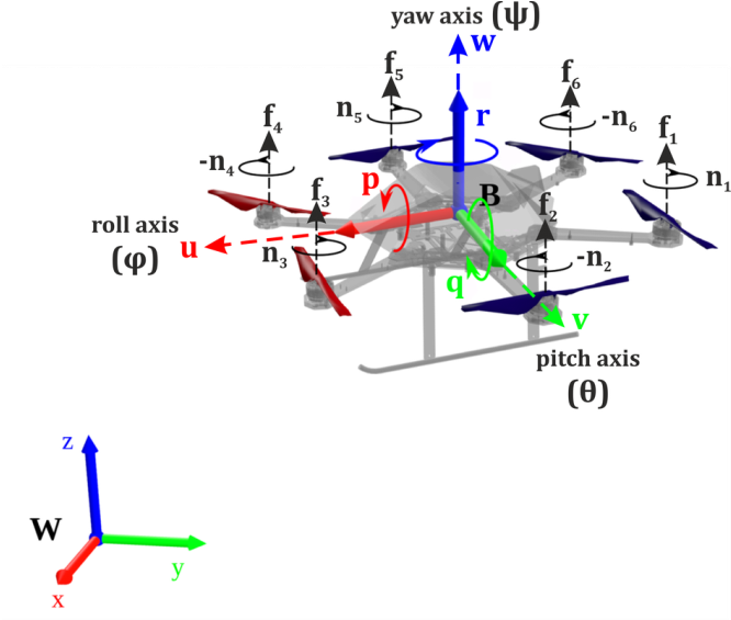
Figure 1: Coordinate frames used for the modeling of the Micro Aerial Vehicle and forces acting on it.
The baseline state variables for the multirotor MAV are:
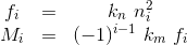
ω=[p,q,r]T marks the BFF-based angular rotation ratesΘ=[ϕ,θ,ψ]T marks the WFF-based rotation anglesU=[u,v,w]T marks the BFF-based velocitiesp=[x,y,z]T marks the WFF-based position{ni,fi,Mi},i∈[1,6] marks the i-th rotor’s rotation speed, thrust force, and moment respectively, and specifically for the hexarotor MAV shown in Figure 1, the generated thrust and moment are given as:
The rigid-body [1] approach is typically followed to derive the dynamics of multirotors: The aerial vehicle’s structure (as well as the propellers’) is supposed to be rigid, and the BFF-origin is selected such that it coincides with the CoM. The active forces and moments (either by external sources such as gravity and aerodynamic drag, or generated by the multirotors’ actuation authorities) are then appended onto this rigid-body of total mass and moment of inertia [2] matrix J .
The Newton-Euler [3] formulation connects the sum of all forces and moment with their effect on the evolution of the aerial vehicle’s BFF rotational ω and translational states v. Maintaining the most significant phenomena, a hexarotors’ dynamics take the form:
The Newton-Euler [3] formulation connects the sum of all forces and moment with their effect on the evolution of the aerial vehicle’s BFF rotational ω and translational states v. Maintaining the most significant phenomena, a hexarotors’ dynamics take the form:
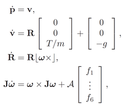
where g marks the acceleration of gravity, T=Σfi is used to mark the sum propellers’ thrust, and the operator |x| marks the skew symmetric calculation. The rotation matrix R (which lies in SO(3) ) represents the orientation of aerial vehicle. The matrix A maps each i-th rotors’ thrust to a generated moment around the rotational axes of the BFF for equal arm lengths l as in Figure 2 (sx,cx stand for sin(x) and cos(x) respectively):
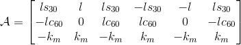
The geometrical reasoning behind the structure of matrix A is shown in Figure 2.
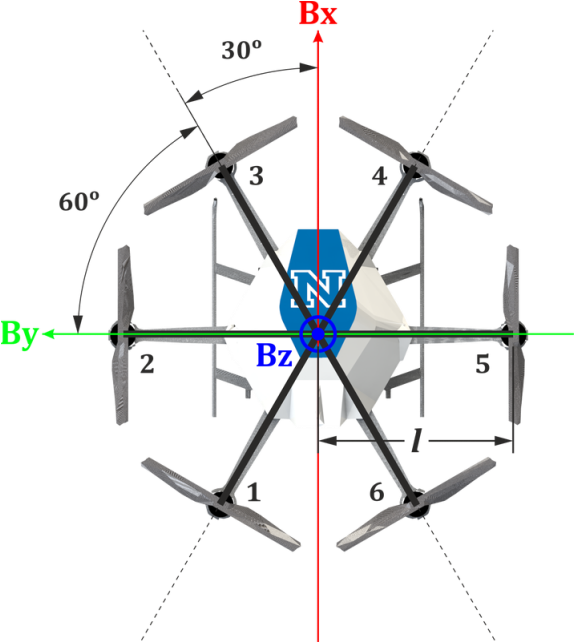
Figure 2: Configuration for a multirotor aerial robot with n=6 rotors.
Less significant phenomena are typically neglected for such an aircraft class and size, especially in slow-speed near-hovering operation. As an additional point it is mentioned that for the rotating propellers (considered rigid and with a moment of inertia Jpzz around the rotation axis), gyroscopic precession introduces the gyroscopic moments expressed in the BFF:
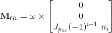
the sum of which becomes negligible for a non-aggressively hovering symmetric multirotor MAV.
Finally, the aerodynamic friction due to the body’s rotational and translational motion through the air can be approximated by the linear model:
Finally, the aerodynamic friction due to the body’s rotational and translational motion through the air can be approximated by the linear model:
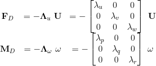
with Λu, Λω diagonal matrices, such that these relationships reflect the fact that the forces and moments contradict (and effectively damp) the aerial vehicle’s current motion.
References
Further study
- M. Kamel, K. Alexis, M. W. Achtelik, R. Siegwart, "Fast Nonlinear Model Predictive Control for Multicopter Attitude Tracking on SO(3)", Multiconference on Systems and Control (MSC), 2015, Novotel Sydney Manly Pacific, Sydney Australia. 21-23 September, 2015.
- K. Alexis, G. Nikolakopoulos, A. Tzes “Model Predictive Quadrotor Control: Attitude, Altitude and Position Experimental Studies”, IET Control Theory and Applications, DOI (10.1049/iet-cta.2011.0348).
Note: This Section was prepared in collaboration with Dr. Christos Papachristos.