Autonomous Resilient Exploration in Subterranean Environments
and other High-Risk Settings
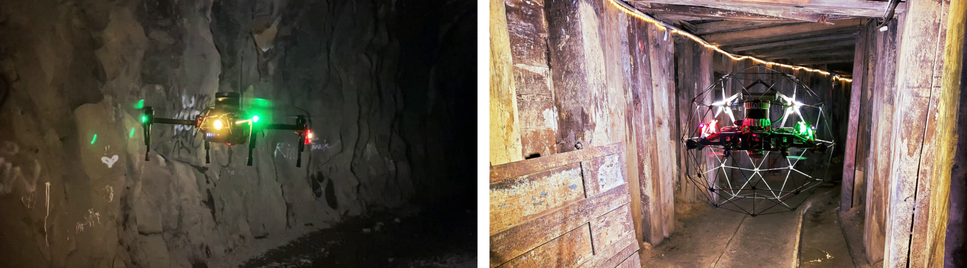
The "Alpha" and "Gagarin" aerial robots exploring subterranean environments using GBPlanner and MBPlanner respectively.
Abstract: This technical brief reviews the application of two algorithmic contributions of our lab in the domain of resilient autonomous exploration path planning with an emphasis on high-risk settings such as subterranean environments. Such exploration missions often have to deal with environments that are simultaneously of very large scale (e.g., km-long), confined and narrow, and often hostile in terms of perceptual degradation and complete lack of communications. Therefore, resilient navigation and exploration behaviors are of paramount importance for the autonomous mapping and search inside such environment configurations which in turn appear often in the context of real-life operational scenarios and deployments. In response to this fact, our lab has contributed two novel path planning methodologies, namely the:
- Graph-based exploration path planner (GBPlanner) [1] and the
- Motion Primitives-based exploration path planner (MBPlanner) [2]
Tailoring the Planning Architecture
In the majority of the literature, including but not limited to previous work of our team [3,4,5] the exploration path planning algorithms proposed attempt to identify iterative solutions by searching within the explored subset of the space available at any time instance. This scheme is particularly applicable in environments of limited scale but - in our experience - turns out to be either ineffective or computationally burdensome in the context of large-scale environments such as an underground mines for example can be (involving mine drifts that are multiple kilometres long). In response to this fact we have proposed a set of planning schemes that employ a bifurcated local/global planning architecture with the local layer exploiting a local dense search approach responsible for efficient exploration path planning around the current robot location, and the global layer utilizing a sparse search method to facilitate autonomous return-to-home and re-positioning towards previously detected frontiers of the exploration space. This is depicted visually for the case of the graph-based exploration planner in Figure 1 below.
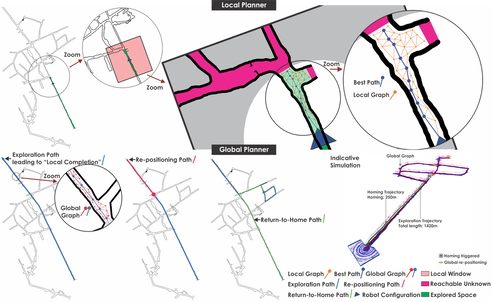
Figure 1. Key steps of the proposed planning methods, hereby presented in the case of GBPlanner. The local planner operates within a window around the current robot location, samples a graph and identifies the path that maximizes the exploration gain. The global planner offers two functionalities, namely a) re-position to the frontier of the exploration space when a ``dead-end'' is reached, and b) return-to-home. For both tasks, the global planner utilizes a graph incrementally built during the robot operation thus saving the time that it would take to sample a new graph from scratch.
Map Representation
A key decision choice of any exploration path planning method is that of environment representation. As the methods incrementally explore and allow the environment to be mapped, the map representation is responsible for three fundamental functionalities, namely:
- To evaluate if a certain point lies in collision-free space and if a certain path segment is collision-free.
- To evaluate how much volume of new so-far unknown part of the map can be perceived from a new candidate point in space that a robot can visit.
- To enable querying for the location of certain objects in the environment and thus facilitate other higher-level functionalities such as artifacts search.
Efficient Local Exploration Path Planning
Provided the abovementioned bifurcated architecture, the local planning layer - both for GBPlanner and MBPlanner - is assigned a "window" of volume around the robot containing a subset of the already explored space (at a given planner iteration) and unknown volume. In this sliding window the local planner employs a strategy to search the configuration space of the robot and find admissible collision-free paths which are evaluated with respect to their exploration gain. For the case of GBPlanner the configuration space is considered to be based on the flat state for a multirotor aerial vehicle ξ = [x,y,z,ψ], while the MBPlanner is specifically tailored to high speed navigation and thus also includes the three velocity states [v_x,v_y,v_z]. As a "search strategy", GBPlanner is employing a local random graph and the process involves the following key steps:
In an analogous but different manner, MBPlanner employs motion primitives to search the configuration space and thus provide admissible collision-free paths that in turn respect and exploit the dynamics of micro aerial vehicles (or other robot configurations if desired and the motion primitives are modified accordingly). As MBPlanner is emphasizing on fast and agile exploration, the end vertex of a path is not assuming zero speed. Thus an admissible path of MBPlanner must not only be collision-free itself but also be such that a "future-safety" path that can stop the vehicle within the currently known collision-free space can be derived. Figure 2 below presents a visualization of how MBPlanner paths could look in a certain environment.
- Sample a random graph G_L within the sliding window of volume assigned to the local planner. An edge is added to the graph only if it is collision-free given a volumetric map representation M.
- Derive Dijkstra-based paths Σ_L starting from the current robot location and spanning towards vertices of the local graph
- Compute the volumetric gain associated with the vertices of this graph and thus evaluate the cumulative exploration gain of the paths in Σ_L.
- Identify the path σ_{L,best} that provides maximum exploration gain and perform some refinement steps to improve its safety.
In an analogous but different manner, MBPlanner employs motion primitives to search the configuration space and thus provide admissible collision-free paths that in turn respect and exploit the dynamics of micro aerial vehicles (or other robot configurations if desired and the motion primitives are modified accordingly). As MBPlanner is emphasizing on fast and agile exploration, the end vertex of a path is not assuming zero speed. Thus an admissible path of MBPlanner must not only be collision-free itself but also be such that a "future-safety" path that can stop the vehicle within the currently known collision-free space can be derived. Figure 2 below presents a visualization of how MBPlanner paths could look in a certain environment.
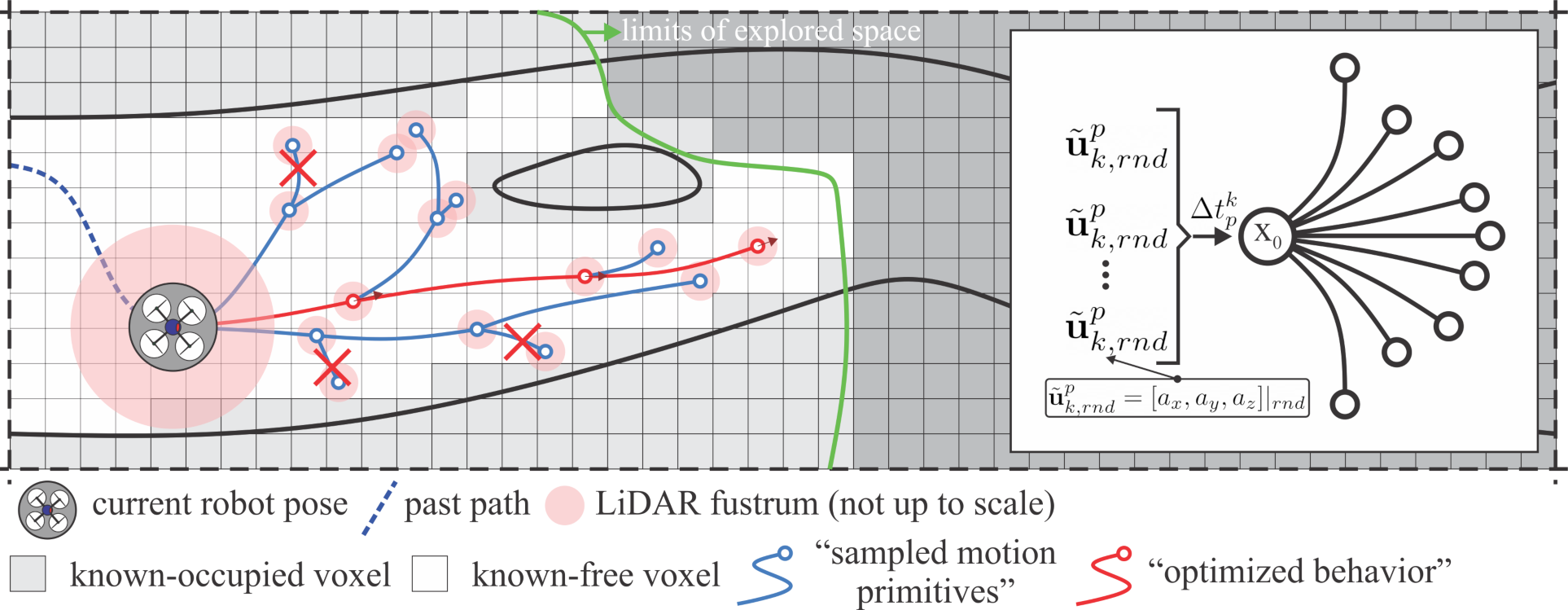
Figure 2. Visualization of the use of motion primitives to search the robot configuration space within the currently explored subset of the map. Each candidate path is evaluated with respect to its associated exploration gain and the best among them is selected to be followed by the robot. MBPlanner is using motion primitives to perform this search process and evaluate candidate paths, whereas GBPlanner exploits a graph-based approach.
In both cases, it was mentioned that the local planner must evaluate the exploration gain of candidate paths. This is performed by the evaluation of a function that takes the form:
In both cases, it was mentioned that the local planner must evaluate the exploration gain of candidate paths. This is performed by the evaluation of a function that takes the form:
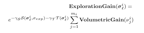
Which in turn implies that the best path is the one that the cumulative new volume to be observed by its vertices (v) as weighted by some factors relating to path length and other metrics relating to directionality and more as detailed in [1,2].
Global Path Planning
With the local path planning layers, both for GBPlanner and MBPlanner, operating only inside a sliding window of space around the robot, efficient search for paths to explore further is possible. However, this choice also implies that by only searching within this space the robot will not be able to execute two fundamental functionalities, namely:
- To return-to-home automatically when for example its battery limits are approaching or when the exploration mission is complete and
- To re-position itself towards a previously identified frontier of the exploration space when - for example - the robot has reached a local dead-end of the environment and thus searching locally is not sufficient to guide the robot towards a previous branching point that might be hundreds of meters apart.
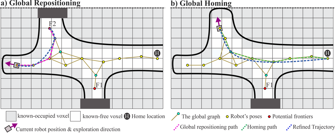
Figure 3. A visualized instance of the global exploration planning layer. Sub-figure (a) depicts a case in which the robot keeps exploring using the local planner until reaching a dead-end. The global planner is then triggered. Depending on the remaining endurance, distance to the frontier, and the volumetric gain, in this example the nearby frontier F2 is selected (instead of F1). MBPlanner would optimize the path to the frontier by considering minimum snap trajectories, while GBPlanner at the moment would employ a different approach to ensure enhanced clearance from obstacles. Sub-figure (b) shows a scenario that the global homing is triggered based on the remaining flight time. Similarly, MBPlanner would optimize the path considering minimum snap trajectories.
Triggering the return-to-home functionality is guided by the remaining flight time of the robot, completion of the mission or an allotted maximum mission time. Re-positioning to a frontier, triggered when the local planner reports inability to explore further, starts with a process of evaluating which of the candidate frontiers is to be selected. With frontiers of the exploration space being detected incrementally as the robot executes the mission (i.e., as it utilizes the local planner), the process is then computationally efficient and involves the evaluation of a Global Exploration Gain taking the form:
Triggering the return-to-home functionality is guided by the remaining flight time of the robot, completion of the mission or an allotted maximum mission time. Re-positioning to a frontier, triggered when the local planner reports inability to explore further, starts with a process of evaluating which of the candidate frontiers is to be selected. With frontiers of the exploration space being detected incrementally as the robot executes the mission (i.e., as it utilizes the local planner), the process is then computationally efficient and involves the evaluation of a Global Exploration Gain taking the form:
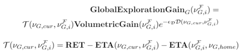
Where essentially the best frontier to be visited is the one that has the maximum anticipated volumetric gain (new volume to be observed) as scaled by a function that relates to the Remaining Endurance (RET) Time of the robot and the Estimated Time of Arrival (ETA) to the frontier and from there back to the home location. This practically implies that if for example two frontiers are of relatively similar anticipated gain but one is better positioned with respect to the current robot location and a path to return to home after visiting that frontier, then it is likely that this frontier will be selected even if its volumetric gain is slightly less.
Path Improvement
GBPlanner implements a path improvement step both at the local and the global stage, while MBPlanner implements an improvement in the global planning stage only as at the local level its paths employ motion primitives tailored to fast navigation. For MBPlanner the global refinement step relates to sparse sampling of the global path and smoothing the derived vertices by applying a minimum snap trajectory calculation [8]. For GBPlanner the path improvement emphasizes on safety as outlined in Figure 4.
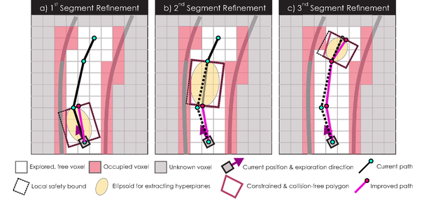
Figure 4. GBPlanner implements a specific approach to improve the robot's safety by adjusting the path so as to ensure it is farther from obstacles - if this is possible. The three necessary steps for this process are visualized.
Complexity Analysis
Extensive details for the computational complexity of the methods are provided in [1,2] and subsequent relevant publications. As a brief summary however, it is worth discussing the main components of complexity at the local and global planner respectively. In the local planner, both for GBPlanner and for MBPlanner the main computational cost relates to evaluating the volumetric gain and checking if a path is collision free. In both cases, the selection of map representation is essential. Voxblox incrementally and dynamically builds Euclidean Signed Distance Fields (ESDFs) out of Truncated Signed Distance Fields (TSDFs) with voxel hashing approach. This in turn means that it costs O(1) to lookup the status of a voxel in the map. Given this fact, the cost for evaluating the volumetric gain in GBPlanner for example is roughtly O(N_V * F_H * F_V * d_max / (r_H * r_V * r) ), where N_V is the number of vertices, F_H and F_V are the horizontal and vertical field of view parameters of the sensor used, d_max the maximum effective range considered for the sensor, r_H * r_v represents the sensor resolution and r the voxel size. In essence, tuning of the voxel size and the selected resolution of the sensor are instrumental for achieving the necessary computational affordability given a particular processing solution onboard the robot. Figure 5 visualizes why this is important. Collision-checking is also significant computationally, although often less, and it has a cost term O(V_{D_R} / r^3 x d_avg /r ), where D_R is the volume assigned to the local planner and d_avg the average length of the path segments in the GBPlanner graph. Analogous terms hold for MBPlanner, while for both planners there are additional cost terms of less significance to be considered. A detailed analysis is available in the respective publications. It is noted that the global planning stage of GBPlanner and MBPlanner are also associated with relevant cost terms with the volumetric gain being the most important in the majority of the times. As the sparse graph of the global layer is built incrementally, the additional cost terms detailed in the relevant planner publications, are often of less significance. As of 2020 we have been using GBPlanner and MBPlanner successfully in both Intel i7-NUC and NVIDIA TX2-based systems conveniently alongside all the rest of the robot autonomy pipeline including a multi-modal LiDAR-Camera-Inertial fusion method for localization and mapping, position control, object detection etc.
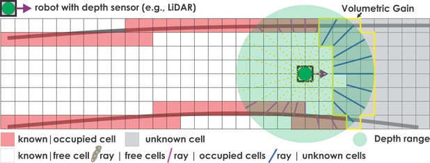
Figure 5. The volumetric gain calculation relies on ray casting. From the current robot pose and given a certain 3D sensor model (here a 2D representation is visualized for simplicity), the algorithm identifies how many voxels in the unknown space can be traversed by any ray casted within the sensor frustum.
Evaluation
Our team has conducted a collection of studies, in simulation and experimentally, to verify both GBPlanner and MBPlanner. Extensive details can be found in the associated publications and other subsequent contributions. In this short technical brief we reference some of the videos relevant to the evaluation of these path planning strategies. As this research is conducted primarily in the context of the DARPA Subterranean Challenge, and other projects relevant for example to underground mine inspection, the environments considered relate to mines, tunnels, underground power plants and more.
GBPlanner & MBPlanner - Indicative Results (First row: GBPlanner|MBPlanner, Second row: GBPlanner|GBPlanner|GBPlanner)
GBPlanner & MBPlanner - Indicative Results (First row: GBPlanner|MBPlanner, Second row: GBPlanner|GBPlanner|GBPlanner)
|
|
|
|
|
|
|
As mentioned GBPlanner has also been deployed to ground systems such as legged platforms as overall results of Team CERBERUS present.
Open Source Code Release
The contributions for Graph-based exploration path planning (GBPlanner) and Motion Primitives-based exploration path planning (MBPlanner) are released as open-source contributions in the form of Robot Operating System (ROS) packages. Those can be found in our repositories:
Furthermore, to support understanding from the perspective of software integration we provide the following diagram (Figure 6) depicting how an aerial robotic system for example utilizing an open-source autopilot (PX4) could implement our exploration autonomy-enabling functionality. In this diagram we assumed the use of other software components, such as a position control (MPC Controller based on [10] - also released as an open-source ROS package) and software for Simultaneous Localization And Mapping. Our methods are compatible with different sensing hardware and localization/mapping software solutions and in fact largely agnostic to specific software choices as long as compatible ROS topics are provided.
- GBPlanner: https://github.com/unr-arl/gbplanner_ros (already released!)
- GBPlanner Simulation Workspace supporting repo: https://github.com/unr-arl/gbplanner_ws
- GBPlanner Simulation Workspace supporting repo: https://github.com/unr-arl/gbplanner_ws
- MBPlanner: https://github.com/unr-arl/mbplanner_ros | (note as of July 6 2020: release is upcoming soon)
Furthermore, to support understanding from the perspective of software integration we provide the following diagram (Figure 6) depicting how an aerial robotic system for example utilizing an open-source autopilot (PX4) could implement our exploration autonomy-enabling functionality. In this diagram we assumed the use of other software components, such as a position control (MPC Controller based on [10] - also released as an open-source ROS package) and software for Simultaneous Localization And Mapping. Our methods are compatible with different sensing hardware and localization/mapping software solutions and in fact largely agnostic to specific software choices as long as compatible ROS topics are provided.
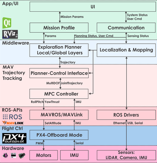
Figure 6. Illustration of ROS-based autonomy stack using (for example) GBPlanner. The diagram is specific to the assumption of using the PX4 open autopilot.
Open Data
In addition we further release associated experimental data for enhanced research reproducibility and verifiability.
Datasets for GBPlanner:
Datasets for MBPlanner:
Datasets for GBPlanner:
- Aerial Robotic Exploration in Underground Mine [link]
- Aerial Robotic Exploration during the Tunnel Circuit of the DARPA Subterranean Challenge [link]
- Aerial Robotic Exploration of the Wampum Room-and-Pillar mine [link]
- ANYmal Exploration of Edgar Mine [link-planner,link-camera]
Datasets for MBPlanner:
- Coming soon!
Contact
For questions with respect to these two planners please contact us at:A complete list of contributors is available at the associated publications' author lists.
References
[1] T. Dang, F. Mascarich, S. Khattak, C. Papachristos, K. Alexis, "Graph-based Path Planning for Autonomous Robotic Exploration in Subterranean Environments", IEEE/RSJ International Conference on Intelligent Robots and Systems (IROS), 2019, Macau, China
[2] Mihir Rahul Dharmadhikari, Tung Dang, Lukas Solanka, Johannes Brakker Loje, Dinh Huan Nguyen, Nikhil Vijay Khedekar, and Kostas Alexis, "Motion Primitives-based Path Planning for Fast and Agile Exploration using Aerial Robots", IEEE International Conference on Robotics and Automation (ICRA) 2020, May 31 - June 4 2020, Paris, France.
[3] A. Bircher, M. Kamel, K. Alexis, H. Oleynikova, R. Siegwart, "Receding Horizon "Next-Best-View" Planner for 3D Exploration", IEEE International Conference on Robotics and Automation 2016 (ICRA 2016), Stockholm, Sweden.
[4] Yamauchi, B., 1997, July. A frontier-based approach for autonomous exploration. In Proceedings 1997 IEEE International Symposium on Computational Intelligence in Robotics and Automation CIRA'97.'Towards New Computational Principles for Robotics and Automation' (pp. 146-151). IEEE.
[5] Yoder, L. and Scherer, S., 2016. Autonomous exploration for infrastructure modeling with a micro aerial vehicle. In Field and service robotics (pp. 427-440). Springer, Cham.
[6] Oleynikova, H., Taylor, Z., Fehr, M., Siegwart, R. and Nieto, J., 2017, September. Voxblox: Incremental 3d euclidean signed distance fields for on-board mav planning. In 2017 Ieee/rsj International Conference on Intelligent Robots and Systems (iros) (pp. 1366-1373). IEEE.
[7] Hornung, A., Wurm, K.M., Bennewitz, M., Stachniss, C. and Burgard, W., 2013. OctoMap: An efficient probabilistic 3D mapping framework based on octrees. Autonomous robots, 34(3), pp.189-206.
[8] Mellinger, D. and Kumar, V., 2011, May. Minimum snap trajectory generation and control for quadrotors. In 2011 IEEE international conference on robotics and automation (pp. 2520-2525). IEEE.
[9] Furrer, F., Burri, M., Achtelik, M. and Siegwart, R., 2016. RotorS—A modular gazebo MAV simulator framework. In Robot Operating System (ROS) (pp. 595-625). Springer, Cham.
[10] Mina Kamel, Thomas Stastny, Kostas Alexis, Roland Siegwart, "Model Predictive Control for Trajectory Tracking of Unmanned Aerial Vehicles Using ROS", Springer Book on Robot Operating System (ROS) – The Complete Reference (Volume 2)